


Text:
MCD_fa_07_antenna-test-eng.pdf
Pictures (Print, CMYK):
Please feel free to order high resolution images via e-mail.
Pictures (Web, RGB):
fa_07_antenna-test-1-web_mcd.jpg
fa_07_antenna-test-2-web_mcd.jpg
fa_07_antenna-test-3-web_mcd.jpg
Project site:
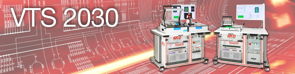
EOL Test system for multifunctional antennas
The wavelengths range between hundreds of meters down to centimeters, the antenna in constant flux and the interferance signals numerous. This is the "work specification" for a multifunctional antenna, which is integrated in modern cars today. The antennas are mostly mounted above the rear window on the vehicle roof. Multifunctional antennas are complex assemblies, found inside mostly fin-shaped plastic housings and enable the performance of mutliple individual antennas. Initially, there is an antenna for terrestrial radio signals, like AM, FM and DAB III, which are responsible for frequencies ranging between a couple KHz up to 100 MHz. Another antenna functions as a global navigation satellite system, GNSS (GPS or GLONASS), which has frequencies of a few Gigahertz. A satellite antenna is integrated optionally, i.e. for the reception of satellite emitted SDARS services or television signals and subsequently a mobile phone antenna. Moreover, for special and commercial vehicles, antennas for CB radio and specially protected transmission types are needed.
1. Ambitious Goals
For car manufacturers and their suppliers the topic "roof antenna" represents a new challenge. Each antenna needs to be examined 100 % before its delivery. A german manufacturer, who produces such antennas for an automobile manufacturer, was in search of a specialist for test technology who especially knows how to deal with enormous frequency ranges between AM up to highest frequency. Bruno Hörter, CEO of the test technology company MCD Elektronik, says: "A test system with this range of functions and frequencies can not be built by just anybody." Due to the fact, that the handling of RF signals is one of MCD´s strengths, they got the contract. Together with a partner company, they built the universal test system for multifunctional antennas within 16 weeks.
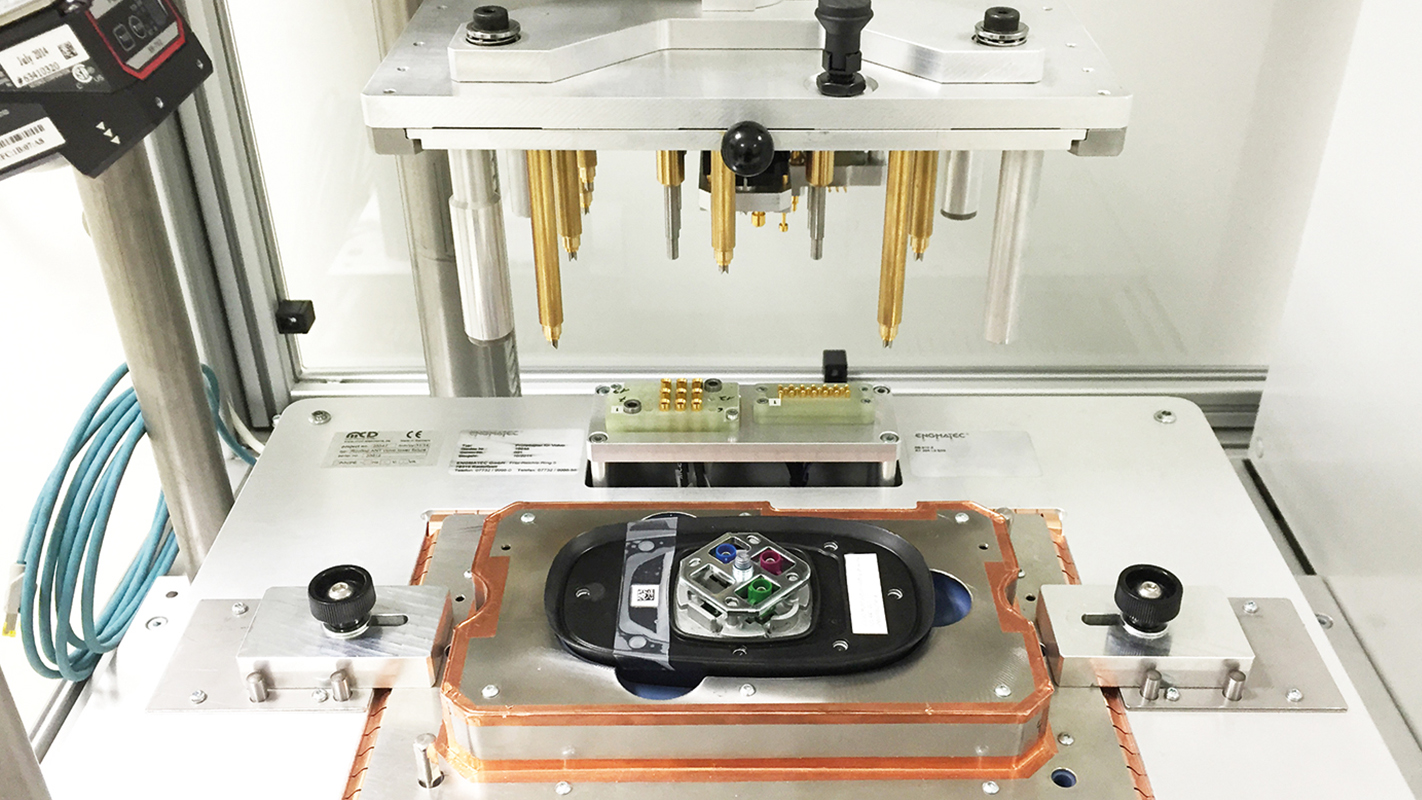
Not only the time plan of the project was challenging, but also the technical requirements were challenging in many aspects. The test station should be able to examine a whole string of different antennas. Therefore, a RF-proof adapter was needed, in which the DUT can be stimulated with various radio signals. MCD used a specially developed helix antenna for sending out radio signals. This antenna serves as a mobile communications antenna and as a transmitting antenna for the stimulation. The mechanics were also challenging: the adapter was designed horizontally adjustable and the test contacts needed to contact the RF connections with a predefined pressure.
2. The Solution
To allow comfortable insertion of the DUT, the test area was generously spaced. As soon as the antenna to be tested was inserted and the hands of the operator were behind the light sensor curtain, the DUT was brought into its test position. The antenna connections are controlled pneumatically and are contacted via special RF-probes. Bruno Hörter: "The key challenge included the shielding of the measurement area against external radiation." The test system was designed universally and and able to be program-controlled for most diverse inspection tasks. A 2D barcode reader identifies the antenna type using the label and therefore triggers the loading of the corresponding test program. The test program communicates with the operator per monitor according to an electronic manual.
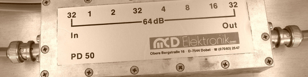
The generation of stimuli and the analysis of the different antenna signals are provided by a network analyzer from Keysight Technologies (formerly Agilent Technologies). The device covers a big frequency range from 100 KHz to 8.5 GHz with a dynamic range of 122 dB. The stimuli are connected via a RF multiplexer and bias tees to the transmitting antenna. A second RF multiplexer reads the responses of the respective antenna via bias tees and passes the RF signal to the network analyzer. This analyzer delivers a two-port S-parameter test set. The four S-parameters are passed together with other measurement results via ethernet to the reliable MCD TestManager.
3. Data for Quality Assurance
The test station delivers extensive data, which is of most importance to the quality assurance. These include: calibration values, high frequency properties, coding of the antenna, special housing characteristics, linearity of measurement curves, wave trap properties, flows in the different working areas and the voltages of power inserters. "The statistical measured values are transferred to the MCD Data Manager and examined for significant shifts using the integrated trend analysis", project manager Axel Aldinger adds.
The Data Manager has a direct connection to the TestManager. The program analyses the measured values and generates statistics and reports. By using a real time database, the evaluation of the measured data is available almost in real-time after a short processing time. The evaluation is produced, either user-controlled or automatically. Extensive filter functions allow different perspectives of the data material. An SQL interface also permits the access to the data material and therefore enables non-standardized, user-specific queries and evaluations.
The most important of the statistical evaluations of the MCD Data Manager include the following:
- Statistics of test results and test duration
- Error statistics (frequency/distribution)
- Statistics of measured values (distribution/variance)
- Analysis of machine and process capability (according to customers algorithm)
The integrated report module supports the user with the design of own evaluations which are saved in project files and can be loaded at any time, if needed.
4. Precision is Triumph
All supply lines in the test station like cables, RF relays and measurement paths are calibrated fully automatically. A graphical analysis via the MCD Toolmonitor was developed for the evaluation of measured values and administration of calibration curves. The toolmonitor is responsible for the recording of curves, adaptation to measurement paths, administration of envelopes as well as identifying the results. Measurements can be processed simultanenously to control tasks with the help of the integrated script engine.
In addition to RF measurements, the DUT is also scanned machanically with sensors. The diagnostic interface of the antenna is also read out and the data transferred to the Test Manager.
The system takes 20 seconds for the complete examination of an antenna. The test station is integrated into the customers´ production line and delivers the edited data to the MES system. Faulty DUTs are disposed and administered via a rejected-parts chute.
When building the test cabin, MCD cooperated, as before, with the measurement specialist Engmatec from Radolfzell, Germany. Engmatec realizes, together with MCD Elektronik, customer-specific solutions for many years in the area automatization as well as test and measurement technology. Engmatec delivers the mechanical components and MCD supplies the corresponding measurement electronics.
__________________________________________________________________
MCD Elektronik GmbH
Hoheneichstr. 52 | 75217 Birkenfeld | Tel. +49 7231 78 405-49 | Fax +49 7231 78 405-10
Ms. Verena Feidy, verena.feidymcd-elektronik.SPAMPROTECTION.de