LVDS Analyzer
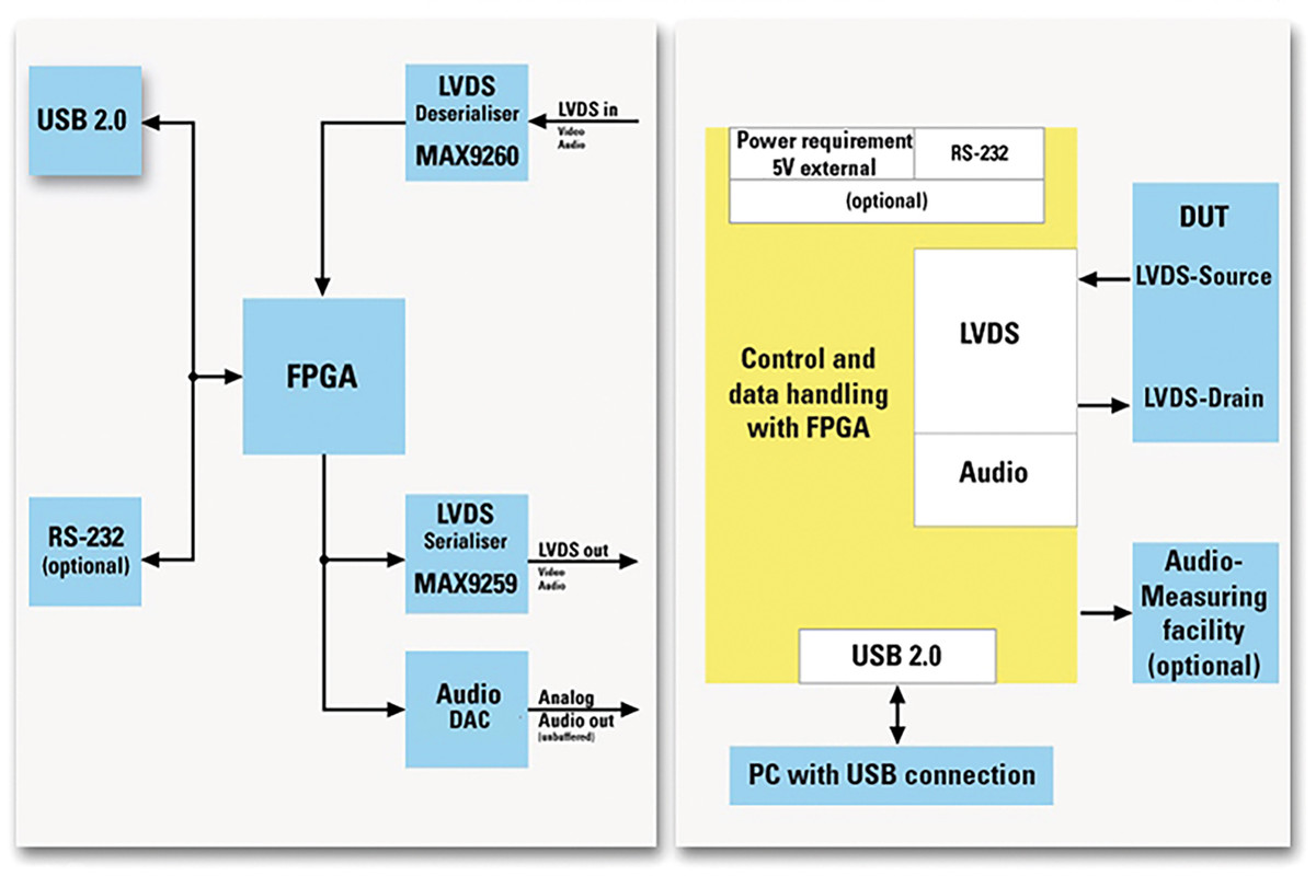
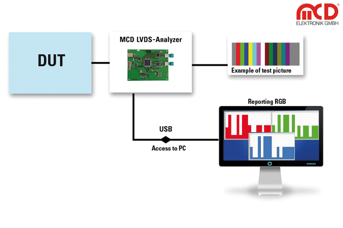
The LVDS Analyzer was developed as part of a test system. With the LVDS Analyzer, the digital color information of any line within a video image can be recorded and evaluated. In addition, a 2-wire LVDS signal from one of four inputs is deserialized and the information contained within is recorded.
The test pattern can be either forwarded 1 on 1 to a reference-display or the own images are issued to test LVDS reduction.
- 5 V power supply via the USB port
- Control and data transfer via USB 2.0
- Use of diagnostic functions of LVDS Switch and Deserializer as:
- Recognition of an LVDS cable error (short-circuit, interruption) on the LVDS output
- Recognition of an existing connection (lock-signal) in the LVDS Deserializer
- Use of Pre-Emphasis on the LVDS output and the equalizer on the LVDS input
- LVDS Switch and Deserializer via USB can be switched on and off during other specific, sensitive testing procedures
LVDS Input
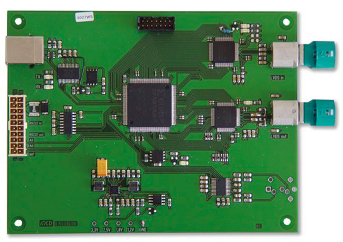
- Deserialization of the LVDS data streams with MAX9260 from Maxim Integrated Products Inc.
- Demapping of the received video data stream into RGB data, HSYNC and VSYNC
- Analog output of the I²S audio data stream via digital/analog converter
- Serialized LVDS outputs of the video and audio input data stream via MAX9259 by Maxim Integrated Products Inc.
- Remapping the output data stream for different target devices (displays) is possible.
- Measurement of the geometry of image acquisition by means of HSYNC, VSYNC and pixel clock
- Detection of a video line at full resolution up to 2047 pixels
- RGB color resolution up to 24 bit
- Capturing a still image is possible through multiple line scanning
- Reduction of the resolution to increase the measurement speed is possible
LVDS Output
- User definable test pattern with up to 2047 pixels width and row height; horizontal gray- and color gradients also possible
- RGB color resolution up to 24 bit
- Mapping of the color and sync signals to the target device (LVDS sink)
- Synchronizable to the sync signals of the input
- Generating its own sync signals HSYNC, VSYNC and DATA ENABLE from the pixel clock
- Availability of the pixel clock from the input signal or its own clock generator (18 MHz, 27 MHz, 29 MHz, 36 MHz, 54 MHz, 58 MHz)
| Size | 130 mm / 100 mm |
|---|---|
| Connecting LVDS input | Rosenberger D4S20G-400A5-Z |
| Connecting LVDS output | Rosenberger D4S20G-400A5-Z |
| Connecting analog audio output | Jack socket 3,5 mm Stereo |
| USB port | USB B |
| Horizontal resolution | 1-16 pixels |
| Vertical resolution | 1 line |
| Color resolution | 8:8:8 RGB (24 bit) |
| Pixel clock | 58 MHz max. |
| Line width | 1 - 2047 pixel |
| Detectable line | Line 1 - 2047 |
| Number of detectable lines | 1 per measurement |
| Synchronization input | HSYNC, VSYNC positive or negative Logic |
| Synchronization output | HSYNC, VSYNC, DATA ENABLE Positive or negative Logic Pulse length with 1 pixel resolution or definable Receive from input |
| Pixel clock output | Receive from input18 MHz, 27 MHz, 29 MHz, 36 MHz, 54 MHz or 58 MHz |
| Current consumption | 200 mA max. |